What is the difference?
Relays with forcibly guided contacts form the connecting element between the load and monitoring circuits as a monitoring element in electronics for functional safety. Because of the possibility of executing safety-related controls with these relays, they are becoming more common. But to apply relays optimally, it is necessary to know the differences to elementary relays and on utilizing these for the particular application.
The big Difference
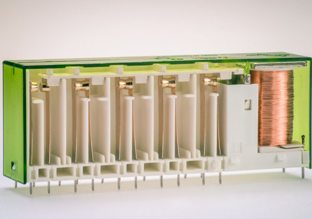
Relays with mechanically force guided contacts, colloquially anderroneously referred to as a safety relays, are a variant within the electromechanical elementary relays. A safety relay, however, is a functional switchgear.The most obvious difference to standard relays is the so called forced guidance of the contacts. The minimum requirements for such a contact set are in accordance with IEC 61810-3, that the contact set consists of at least one NC contact and one NO contact. The contacts are mechanically linked, so that NO and NC contacts must never be closed at the same time. This functionality must be guaranteed over the entire relays life.
During an opening failure of a contact, for example, due to contact welding, the dysfunctional contact is blocking the entire set of contacts. With a welded NO contact it is no longer possible that one of the NC contacts in the system can fall back into its basic position. This functionality is also provided if an NC contact would weld, because then the system is blocked so that in driving the relay coil the relay drive is no longer capable of closing the NO contacts.
Using two relays in series with mutual monitoring ensures a safe off and prevents a reconnection of the load. Normally, in that way common cause failure can be excluded. In a so-called “non-opening error” a minimum opening width of 0.5 mm of the counter-acting contacts must be maintained. This system makes it easy to link load circuits of an electronic control system with the control circuits and thus to monitor the load circuits, resulting in a very high degree of diagnostic coverage.
Other construction requirements
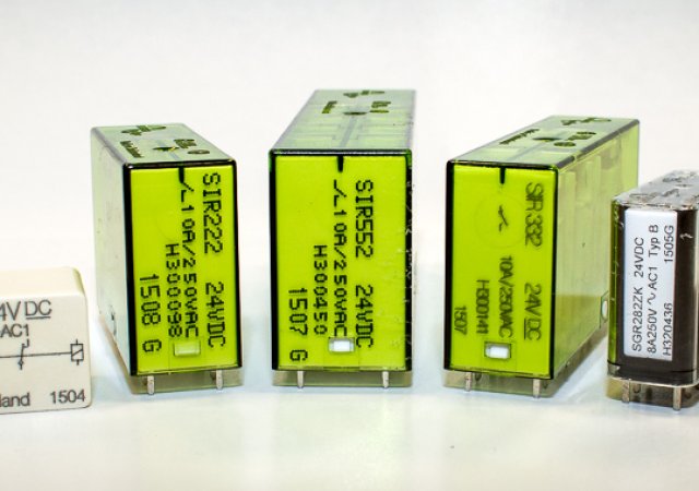
To secure forced guidance it is necessary to consider other design specifications. For example it is impossible to eliminate all kinds of errors. This includes in particular the spring breakage of a contact spring. For this reason, all contacts are embedded in contact chambers, which prevent short circuits in case a spring breaks and parts of the contact spring wander. The breaking of the armature plunger would also lead to loss of forced guidance, oversizing the armature plunger can prevent this. These design measures are, inter alia, reasons why the relays with forcibly guided contacts are often of larger volume than comparable standard relays.Since the loss of insulating properties is also a dangerous error, an insulation test must be passed by the end of the “total” life. This means, relays with forcibly guided contacts should not have an insulation failure as far as it is humanly possible to judge.
This principle can be used as equipment condition monitoring of electronic controls in applications. According to the closed-circuit principle, as a design principle in applications of functional safety, a controller must be designed such that it falls back in a defined starting position after being switched off and the switching status is checked before the restart of the application. Consequently a welded contact would cause all normally closed contacts of the relay to no longer fall back into their normal position, as described above. When checking before restarting the system would be recognizing the failed state and the restart could not be carried out. For example, a contact welding can now occure, which can not generally be excluded, but this “error” does not lead to a malfunction of the system, for example, the restart of a punch press. This operating principle is the reason why remanence or bistable relays are not possible in these applications.
The Consequences
The use of relays according to IEC 61810-3 has consequences. Due to forced guidance and oversizing comparatively more drive power is required. Compared to a relay with two changeover contacts nearly double the coil capacity is needed for the version with forced guidance. To compensate for the higher energy consumption as much as possible, there is the possibility to use relay coils exactly tailored to the application. In addition the the relay in the application can be operated with the holding energy after the excitation. Therefore customized coils in conjunction with setback circuits (for example, PWM) are a great way to meet the demands for low self heating and energy-efficient design.
By linking load and logic in the relay, the issue of contact reliability is not insignificant. Among other things, the contact chambers prevent the pollution of adjacent contacts, but especially with very low switching cycles or very light loads in the monitoring circuits the selection of the contact types must be considered. Contact designs like crown and notched crown contacts, which allow multiple contacting, increase the contact reliability. In design, the developer can then configure the contacts so that the distances between the litter louts and neat guys are large. Special contact loading of relays with extended clearance and creepage distances within the relay are an additional option the relay manufacturer can provide.
Since the introduction of the new Machinery Directive, statements on the statistical probability of failure have to be made, apart from the purely function-related questions. For relays with forcibly guided contacts, it is usually possible to make statements about the probabilities of dangerous failure, the so-called B10d value. These are available for the load types AC-15 and DC-13, which are calculated according to the IEC 61810-2-1.
Rules of thumb, defaults or the use of “house rules” which are partially found in application standards or equipment standards, should be avoided. Consulting the manufacturer of relays quickly brings clarity with proofed values.
Relays with forcibly guided contacts are proven components in the implementation of monitoring controls. The range of applications stretches from the machine construction to lift applications, process industry, medical technology and to railway applications. A dedicated product selection, together with the relay manufacturer, helps the relay application to achieve the best possible performance.


